
Alok Menghrajani
Currently: security consulting and lecturer.
Previously: security engineering at Square Block. Co-author of Hack (the programming language) and put the 's' in https at Facebook Meta. Maker of various CTF puzzles.
This blog does not use any tracking cookies and does not serve any ads. Enjoy your anonymity; I have no idea who you are, where you came from, and where you are headed to. Keep the dream of an Internet from times past alive.
Home | Contact me | Github | RSS feed | Consulting services | Tools & games
I decided to flash an Atmel at89s4051 microcontroller using an Arduino. People have used the Arduino as a programmer in the past, but I didn't find detailed information for programming this specific Atmel, so I did things mostly from scratch (only way to really learn how things work anyways).
I picked the at89s4051 mostly because people before me had picked it for their projects, such as the heart kit (i.e. I had a bunch lying around). The at89s2051 is exactly the same as the 4051, except it has 2Kb of flash memory instead of 4Kb).
I enjoy playing with microcontrollers because the code runs directly on the hardware, there's usually no operating system.
The hardware
The at89s4051 costs about a dollar and is based on the 8051 instruction set (developed by Intel in 1981). The microcontroller has 15 I/O lines, two timers, analog comparators, PWM and UART; sounds very similar to an Arduino, right? The chip is fully static and can take a clock between 0 and 24Mhz.
If you want to program you own microcontroller, you can pick almost any chip. You can choose from a variety of architectures such as the 8051, PIC, AVR, ARM, etc. The chips usually cost between a few cents to a few dollars (as long as you stay away from the fancy stuff).
Note: I also had a few C variants lying around (at89c2051 and at89c4051). The C variants have the same pin layout but are not as easy to program due to the lack of ISP.
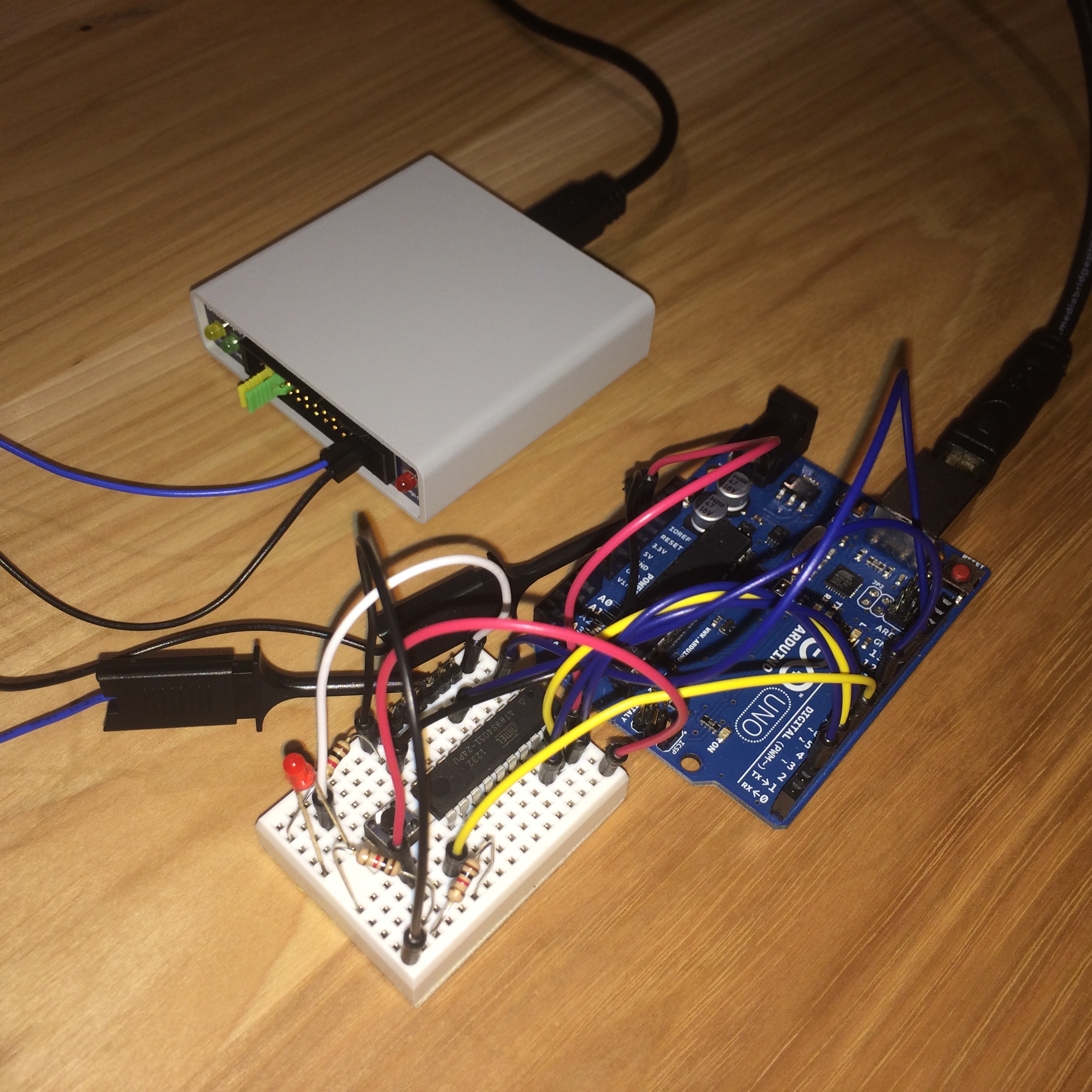
Besides the microcontroller, I used the Ultimate Arduino Microcontroller Pack. The useful components from the pack for this project were the Arduino UNO (you can pick any Arduino variant), breadboard (I used the small stamp sized one for fun), resistors, push button, LEDs and jumper wires. It;s cheaper to buy exactly the parts you need but having a starter kit is very convenient.
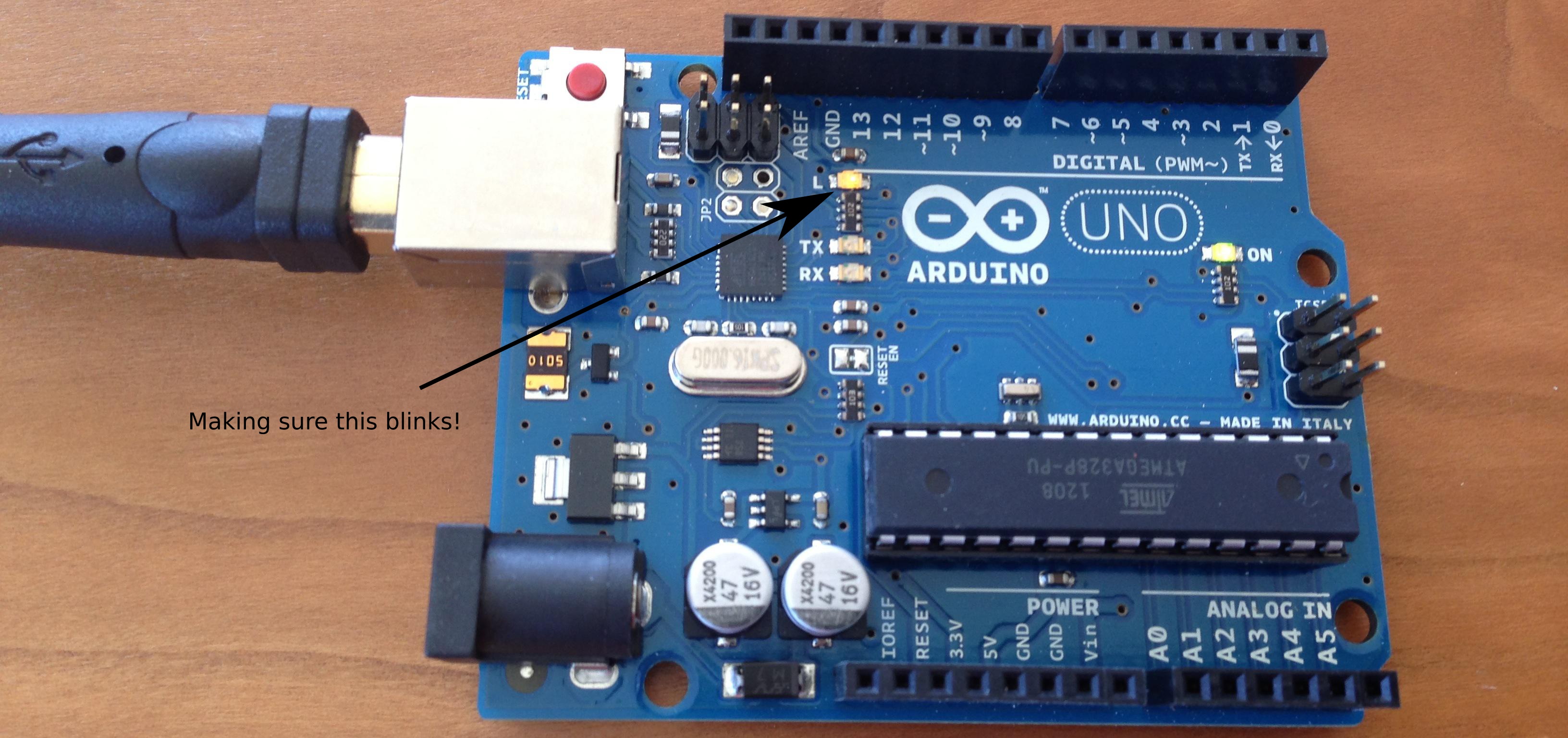
Making sure the Arduino works
The first step is to make sure the Arduino works. The exact installation process is beyond the scope of this article. I connected the Arduino to my laptop, installed the software and selected one of the samples (Blink). After uploading the code to the Arduino, I had a the onboard LED (which soldered with port 13) that was blinking every second:
Programming modes
The at89s4051 has two programming modes: parallel and ISP. In parallel mode, you need to power the chip with a 5V input (Vcc) but use a 12V signal on the RST/Vpp pin. Having to deal with two different voltage levels on the same pin is a little annoying (can be accomplished with a transistor). I decided to use the slower ISP programming mode.
In ISP mode, you set RST to 5V and then use SCK and MOSI to write data (one bit at a time) or SCK and MISO to read data (also one bit at time). It's a very simple protocol and since SCK tells the microcontroller when the data is ready, you can flash the memory at any speed you desire. You can even use a switch to program it manually!
When programming in ISP mode, you need to provide a clock signal to XTAL1. The documentation says 3-24 Mhz. As far as I can tell, this range is very conservative. I was able to use a signal in the 500hz range. The final code uses 8Mhz. You can also use a crystal with two capacitors.
Keep in mind the chip erase function (which resets the content of the flash) needs to be called before being able to re-program the memory. I was expecting to be able to write to specific locations in the flash without having to clear the entire memory.
Hand assembling a small program
I wrote the following piece of assembly code to blink a LED connected to P3.0.
start:  mov   0xb0, #0x00     // 0xb0 maps to port 3
l1:     mov   r1, #0xff
        mov   r0, #0xff
l2:     djnz  r0, l2
        djnz  r1, l1
        mov   0xb0, #0x01
l3:     mov   r1, #0xff
        mov   r0, #0xff
l4:     djnz  r0, l4
        djnz  r1, l3
        sjmp  start
I then hand assembled this code (it's only 24 bytes) and computed the relative offsets for the five jumps:
    0x75, 0xb0, 0x00, // mov 0xb0, 0x00
    0x79, 0xff,       // mov r1, 0x10
    0x78, 0xff,       // mov r0, 0xff
    0xd8, 0xfe,       // djnz r0, -2
    0xd9, 0xfc,       // djnz r1, -4
    0x75, 0xb0, 0x01, // mov  0xb0, 0x01
    0x79, 0xff,       // mov r1, 0x10
    0x78, 0xff,       // mov r0, 0xff
    0xd8, 0xfe,       // djnz r0, -2
    0xd9, 0xfc,       // djnz r1, -4
    0x80, 0xe8,       // sjmp   -24
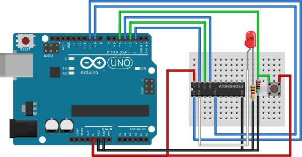
Connecting the microcontroller
The microcontroller is powered by the Arduino. I generally avoid using pins 0 and 1 on the Arduino because they are shared with the serial console on the UNO.
| Arduino | at89s4051 |
| 5V | pin 20 (Vcc) |
| GND | pin 10 (GND) |
| pin 2 | pin 19 (SCK) |
| pin 3 | pin 18 (MISO) |
| pin 4 | pin 17 (MOSI) |
| pin 9 (PWM) | pin 5 (XTAL1) |
| pin 11 (RST) | pin 1 (RST/VPP) |
| pin 2 is connected to a LED + 1kΩ resistor in series | |
| pin 5 is connected to a push button + 2kΩ pull-down resistor |
Ideally, you should use pull up resistors (and also a capacitor between VCC and GND to stablize the power). I however decided to just connect the pins, it works well enough for my use-case.
The code
Here is the full Arduino code:
/**
 * Code to interface with an Atmel 8501 microcontroller (e.g. at89s4051).
 *
 * Uses the ISP to talk to the chip. The code waits for the button to be
 * pressed and then programs the microcontroller to blink a LED. The
 * Arduino provides (a slow) clock signal to the microcontroller.
 *
 * See https://quaxio.com/programming_an_at89s4051_with_an_arduino/
 */

// Pin mapping
int sck = 2;
int miso = 3;
int mosi = 4;
int button = 5;
int xtal = 9; // PWM
int ignored = 10;
int rst = 11;
int led = 13;

void setup() {
  pinMode(xtal, OUTPUT);
  pinMode(ignored, OUTPUT); // timer1 is connected to pins 9 and 10.
  TCCR1A = 0b01010000; // CTC
  TCCR1B = (TCCR1B & 0b11100000) | 0b01001; // CTC + no prescaling
  OCR1A = 0; // 8Mhz

  pinMode(rst, OUTPUT);
  pinMode(mosi, OUTPUT);
  pinMode(sck, OUTPUT);
  pinMode(miso, INPUT); // tri-state
  pinMode(button, INPUT);
  pinMode(led, OUTPUT);

  digitalWrite(rst, LOW);
  digitalWrite(mosi, LOW);
  digitalWrite(sck, LOW);
  digitalWrite(led, LOW);

  Serial.begin(9600);
}

void loop() {
  Serial.print("Push button to start programming\n");
  while (1) {
    int t = digitalRead(button);
    if (t == HIGH) {
      program();
      Serial.print("Push button to start programming\n");
    }
  }
}

void program() {
  // Enabling ISP
  Serial.print("Enabling ISP\n");
  digitalWrite(led, HIGH);
  digitalWrite(rst, HIGH);
  digitalWrite(sck, LOW);
  delay(50);

  // Program enable
  Serial.print("Program Enable\n");
  ispSend(B10101100);
  ispSend(B01010011);
  ispSend(0);
  ispSend(0);

  // Chip erase
  Serial.print("Chip erase\n");
  ispSend(B10101100);
  ispSend(B10000000);
  ispSend(0);
  ispSend(0);

  // Read atmel signature bytes
  int ok = true;
  Serial.print("Atmel Signature: ");
  ispSend(B00101000);
  ispSend(0);
  ispSend(B00000000);
  int t = ispRecv();
  ok = ok && (t == 0x1e);
  Serial.print(t, HEX);
  Serial.print(" ");

  ispSend(B00101000);
  ispSend(0);
  ispSend(B00000001);
  t = ispRecv();
  ok = ok && (t == 0x43);
  Serial.print(t, HEX);
  Serial.print(" ");

  ispSend(B00101000);
  ispSend(0);
  ispSend(B00000010);
  t = ispRecv();
  ok = ok && (t == 0xff);
  Serial.print(t, HEX);
  Serial.print("\n");

  if (!ok) {
    Serial.print("Did not receive expected signature, aborting!");
    digitalWrite(rst, LOW);
    digitalWrite(led, LOW);
    return;
  }

  // Write code
  int addr = 0;
  byte code[] = {
    0x75, 0xb0, 0x00, // mov 0xb0, 0x00
    0x79, 0xff,       // mov r1, 0x10
    0x78, 0xff,       // mov r0, 0xff
    0xd8, 0xfe,       // djnz r0, -2
    0xd9, 0xfc,       // djnz r1, -4
    0x75, 0xb0, 0x01, // mov  0xb0, 0x01
    0x79, 0xff,       // mov r1, 0x10
    0x78, 0xff,       // mov r0, 0xff
    0xd8, 0xfe,       // djnz r0, -2
    0xd9, 0xfc,       // djnz r1, -4
    0x80, 0xe8,       // sjmp   -24
    0x00, 0x01, 0x02, 0x03,
    0x04, 0x05, 0x06, 0x07 // pad to 32 bytes
  };
  writeCode(0, code);

  // Read back the code bytes
  byte buf[32];
  readCode(0, buf);
  for (int i=0; i<32; i++) {
    ok = ok && buf[i] == code[i];
  }
  if (!ok) {
    Serial.print("Did not receive expected bytes, aborting!");
    digitalWrite(rst, LOW);
    digitalWrite(led, LOW);
    return;
  }

  Serial.print("Success\n");
  digitalWrite(rst, LOW);
  digitalWrite(led, LOW);
  return;
}

// Write 32 bytes of data
void writeCode(int addr, byte* data) {
  ispSend(B01010000);
  ispSend(addr >> 8);
  ispSend(addr);
  for (int i=0; i<32; i++) {
    ispSend(data[addr + i]);
    Serial.print(".");
  }
  Serial.print("\n");
}

// Read 32 bytes of data
void readCode(int addr, byte* data) {
  ispSend(B00110000);
  ispSend(0);
  ispSend(0);
  for (int i=0; i<32; i++) {
    data[addr + i] = ispRecv();
    Serial.print(data[addr + i], HEX);
    Serial.print(" ");
  }
  Serial.print("\n");
}

// Send one byte
void ispSend(byte value) {
  for (int i=7; i>=0; i--) {
    ispSendBit(value >> i);
  }
}

// Send one bit
void ispSendBit(int value) {
  int t = value & 1;
  delay(1);
  digitalWrite(mosi, t);
  digitalWrite(sck, HIGH);
  delay(1);
  digitalWrite(sck, LOW);
}

// Receive one byte
int ispRecv() {
  int r = 0;
  for (int i=0; i<8; i++) {
    int t = ispRecvBit();
    r = (r << 1) | t;
  }
  return r;
}

// Receive one bit
char ispRecvBit() {
  delay(1);
  digitalWrite(sck, HIGH);
  delay(1);
  digitalWrite(sck, LOW);
  return digitalRead(miso);
}
Screenshots
Programming is really fast, takes a second or two.
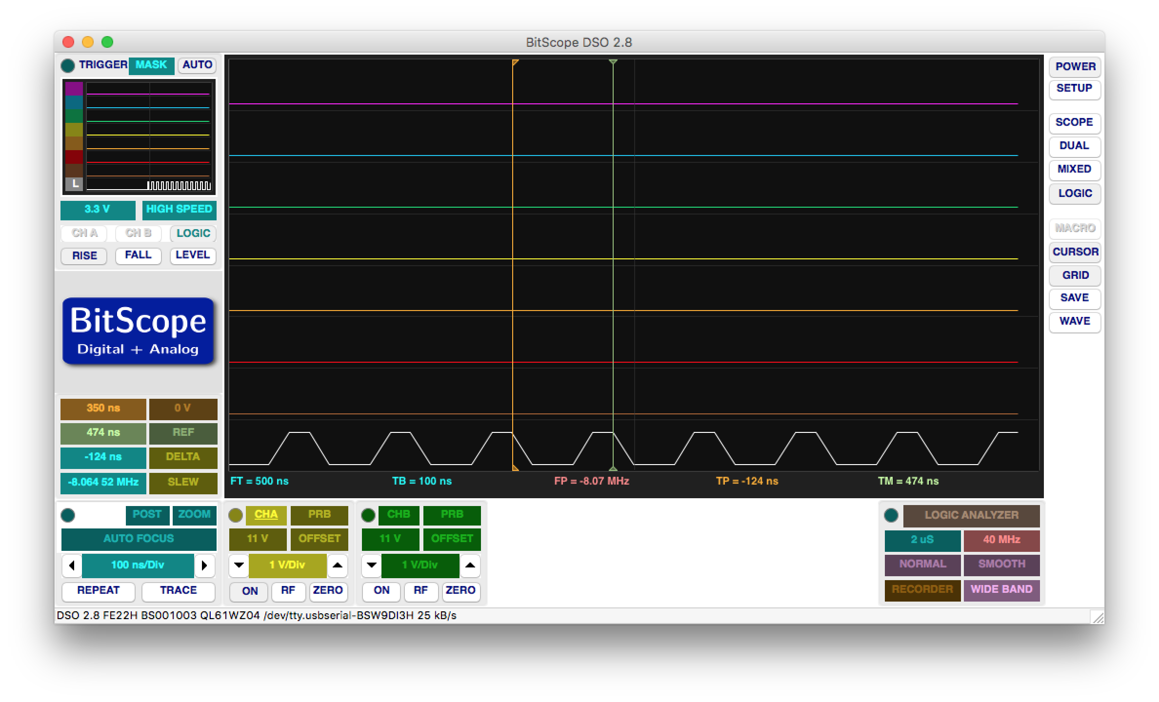
I used a BitScope oscilloscope to check the XTAL1 signal. The square wave starts to get deformed at this speed.
Links
- at89s2051/at89s4051 technical sheet
- 8051 instruction set
- Digikey, where I buy all my electronic components.
- heart of love
- TNeo RTOS, Dmitry Frank's operating system for MCUs in case you decide you want an operating system.
- BitScope: a cheap, USB oscilloscope. Can also serve as a signal generator.