
Alok Menghrajani
Currently: security consulting and lecturer.
Previously: security engineering at Square Block. Co-author of Hack (the programming language) and put the 's' in https at Facebook Meta. Maker of various CTF puzzles.
This blog does not use any tracking cookies and does not serve any ads. Enjoy your anonymity; I have no idea who you are, where you came from, and where you are headed to. Keep the dream of an Internet from times past alive.
Home | Contact me | Github | RSS feed | Consulting services | Tools & games
In high school, I built a binary adder which uses no silicon components and no transistors. As a student at Chamblandes, Pully, Switzerland, my physics teacher gave me a few tips.
Instead of using transistors or semi-conductor, I used solid state relays, LEDs, switches and resistors. The idea was to built something similar to early computers.
At the time, I hadn't yet learned about circuit design. I also didn't know the link between boolean algebra and computing. I therefore designed this piece of hardware using intuition and lots of trial and error (on paper). One of my main challenges was to reduce the number of relays needed, as these components consume a lot of energy and are expensive.
Computers and calculators typically perform binary computations. Binary is a different way to represent numbers. Humans have ten fingers, our natural instinct is therefore to count in a decimal system. We count from 0 to 9 and then from 10 to 19 and so on. Our numbers are powers of tens. 25 is two times 10 and five times 1. Binary is similar but with powers of two. 101 in binary becomes one times 4, zero times 2, and one times 1. Totalling 5.
My hardware uses relays. These are like switches, but instead of being controlled mechanically like a keyboard, they are controlled by an electric current. When the current flows through a relay, it closes (due to electromagnetic interaction). When the current stops, it opens (thanks to a spring). You can see the three relays on the pictures below.
The first part of the project involved drawing the circuits on a sheet of paper. This was interesting because I didn't know how many relays I would need; my first design required eight of them. I then reduced the number to three.
I then ordered the components and soldered them together. The major difficulty I encountered was working with all the wires. I used a piece of balsa wood, which is soft and easy to work with. It was fun hearing the relays click whenever the inputs to the adder changed!
Fun fact: I had to use the power supply from a Commodore 64 (9V, 1A) because of the power consumption of the relays.
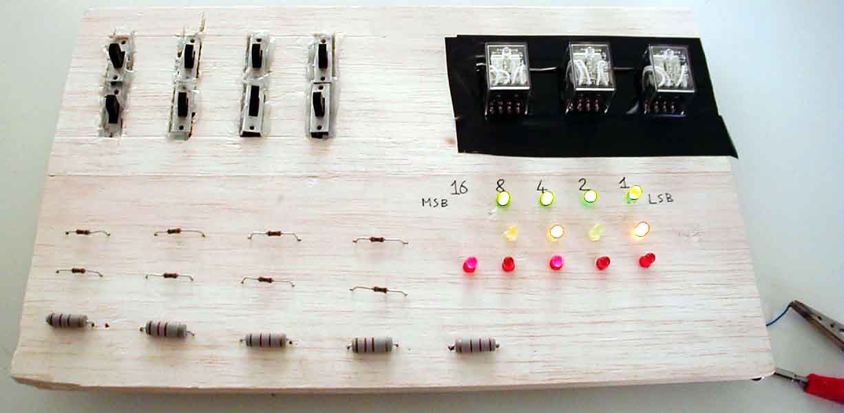
Front side of the adder
On this picture, you can see the various components I used: 8 switches (top left), 3 relays (top right) and 13 LEDs and resistors.
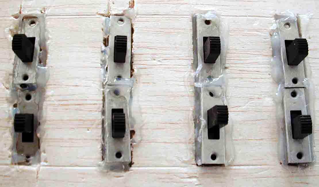
Input to the adder
The adder is controlled by these 8 switches. Each switch controls a power of two. Balsa wood is easy to cut in one direction but not both directions. I had to resort to using glue.
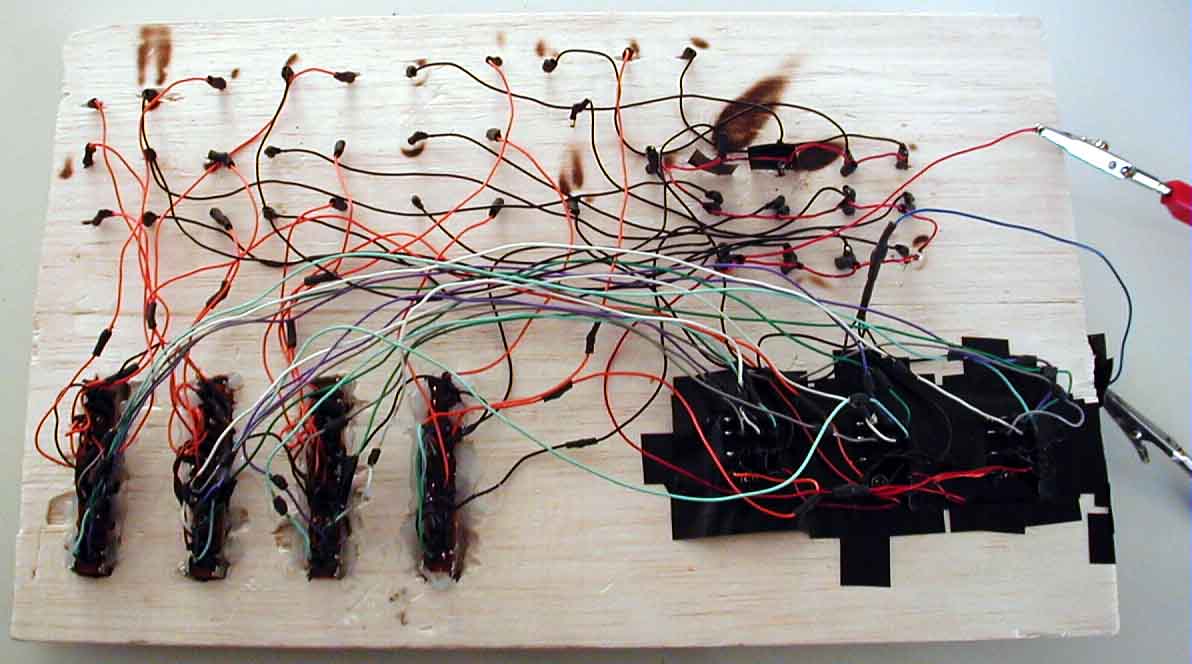
Back side of the adder
The back side was a big mess of connections. Burn marks from using a lighter for the heat shrink tubing. It's better and safer to use a heat gun instead.
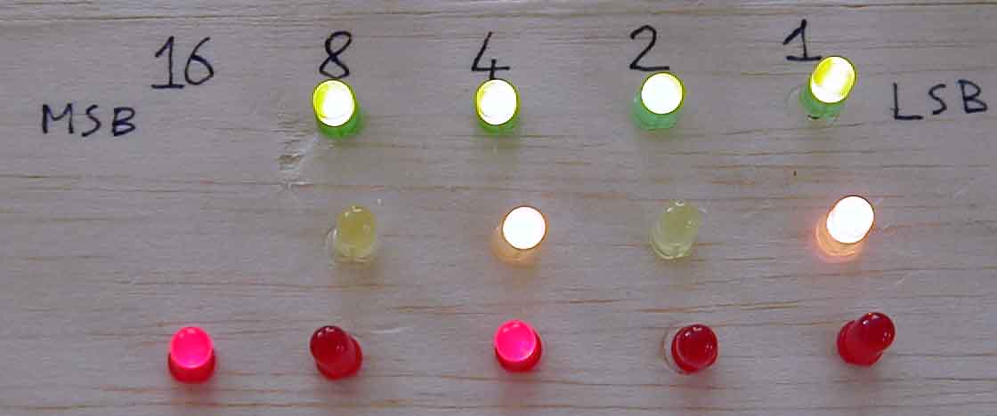
Sample calculation
We perform a sample computation: 15 + 5 = 20.
links
- inside the binary adder (ppt, includes circuit diagram)
- Binary numeral system (wikipedia article)
- Relay (wikipedia article)
- binary marble adding machine